
Lightgun Lichtknarre > LEDs building
Whats going on here?
Here you can learn how to build LEDs for the “Lichtknarre”-lightgun software.
Information on the “Lichtknarre”-lightgun software can be found here:
https://geekonarium.de/en/lightgun-lichtknarre-for-the-wii-remote-on-your-pc-computer/
no warranty
This project has not been developed to comply with industry standards, so we do not guarantee anything and will not pay for damages or other problems.
Beware: Only use the circuit if the box is closed and do not touch the LEDs when powered.
Show me!
Beware the circuit it outdated in this video tutorial, because the seller changed specifications. Use specifications from this tutorial.
Do i realy need todo that much effort?
Depends. If you realy want the ultra Version which works on Beamer etc than maybe you should build this. Since 0.9.8 we have also the BAD-LED mode. Low powered IR-LEDs should work in most cases also now! Some people had reported that 980nm LEDs which are also used in the Wii sensorbar work well for normal TV/monitor sizes without BAD-LED mode. Never validated this, but just in case:
See BAD-LED mode:
https://youtu.be/2AiFrcu059I?t=962
You can also lookup the tutorials of other users:
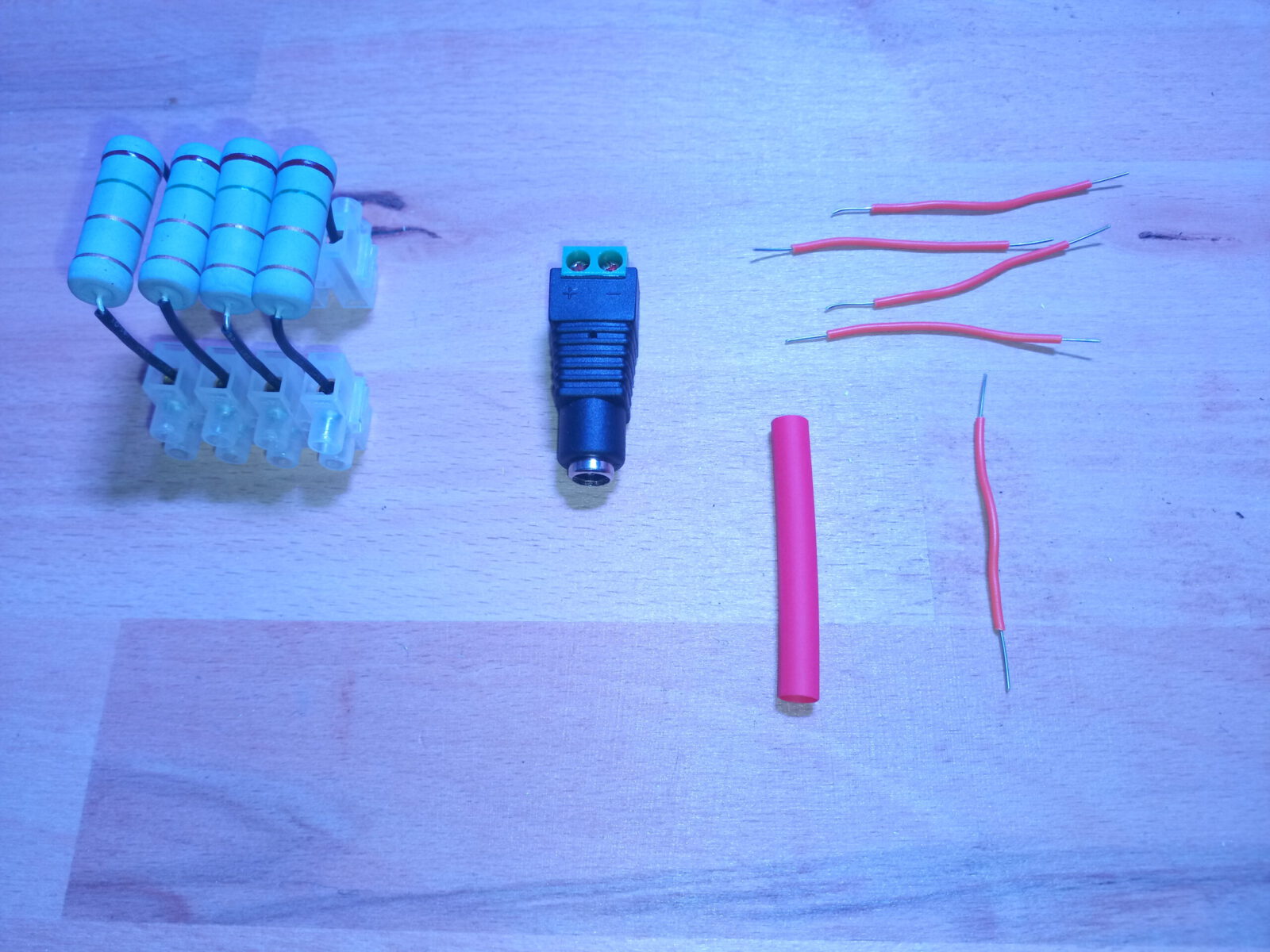
Shopping list
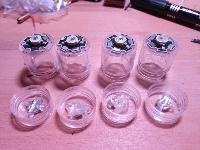
- 4 x 90° lenses
- 4 x IR 850 nm High Power LEDs
- ebay
1.7V-1.9V- Seller changed specs. Now use 2.4V with 1 Ohm resistor:
- 850nm IR LEDs have not been tested yet. (Best would be 980nm)
4 x 1.5 Ohm resistors- cable
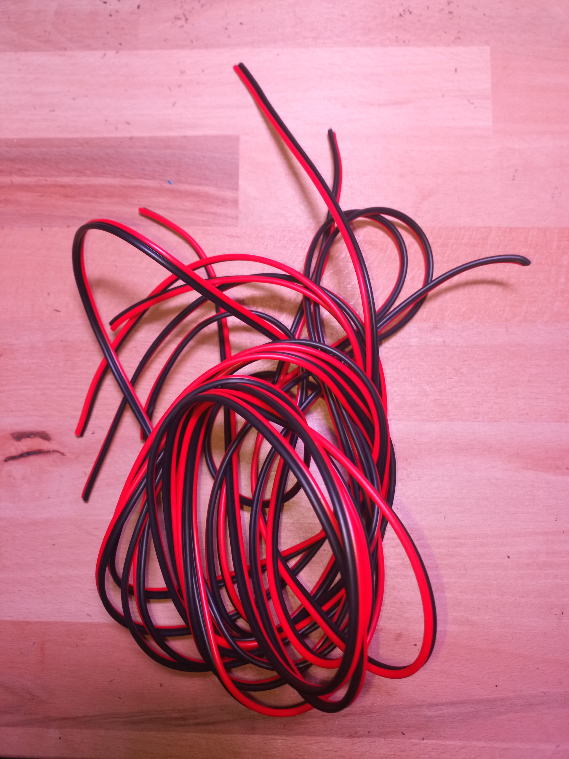
- Amazon
- Music cables are good because +ve and -ve are together.
- 3V power adaptor which can output 800mA * 4 LEDs = 3200mA
- Amazon
- This AC-Adapter outputs 3000mA but i dont find a better one 😀
- Amazon
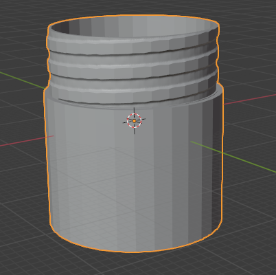
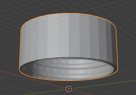
- 4 x plastic cases (or use 3d printed parts):
- Amazon
- diameter: 24mm, height: 30mm
- round
- with a screw cap
- Lustre terminal, which fits in the plastic case.
- electronic cables
- round neodym-magnets
- Amazon
- 6mm diameter
- plastic distribution box (look 3d printed parts)
- Power supply adapter
Equipment
- soldering iron
- hot glue
- 2mm drill
- super glue
- and so on
3D print parts
Enclosures for electronics as 3d prints can be found here.
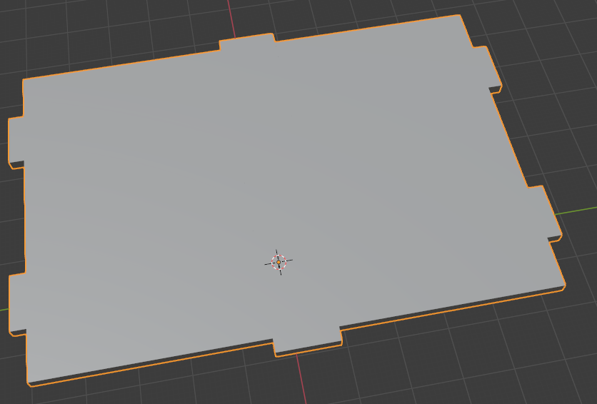

Housing is compatible with power supply adapter thanks to:
https://www.thingiverse.com/thing:2518532
Theory
We want to create following the circuit:
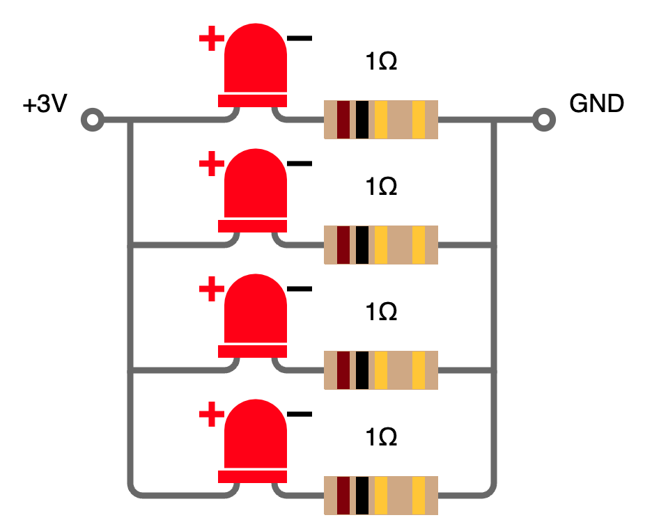

Here you can change the configuration of the circuit if you like: LED-Calculator
Assembly
All steps has to be repeated 4 times, because we are building 4 LEDs.
1. LEDs > case drilling
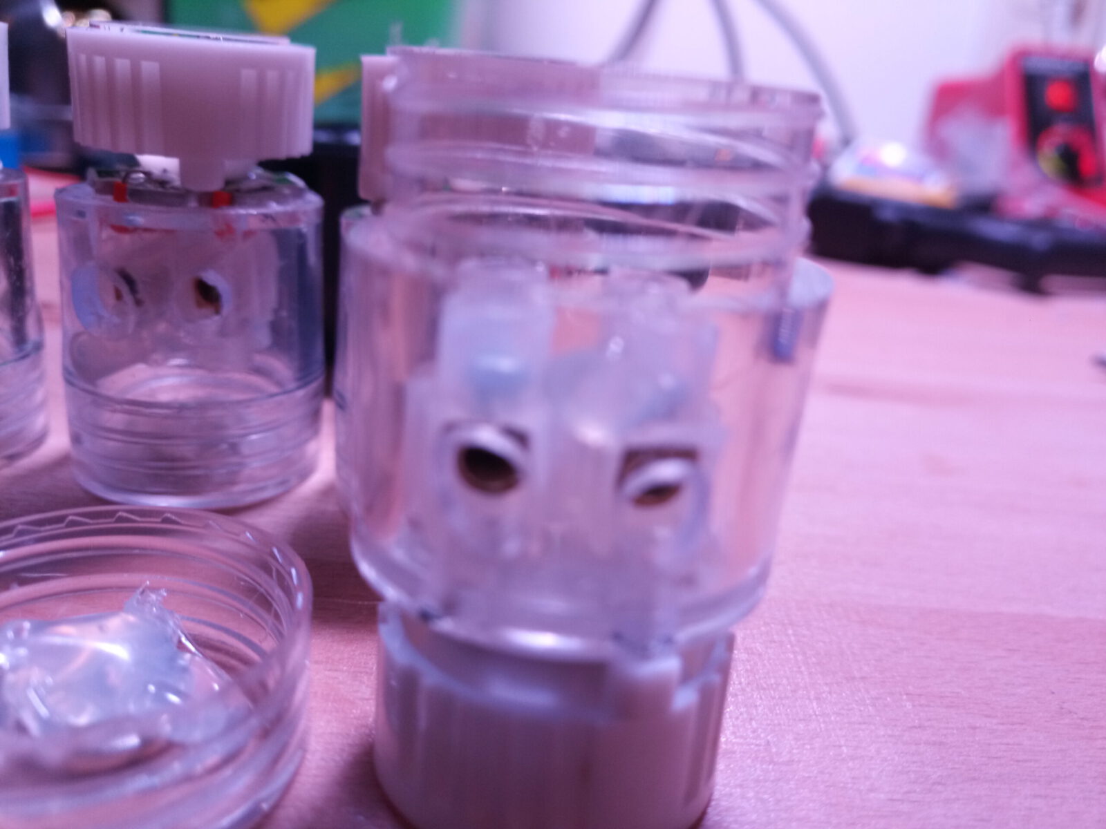
- Put the LEDs on the closed site of the casing. Not on the side with the screw cap.
- Mark 2 points. The holes should reach the + (positive) and – (negative) pole.
- Drill the holes.
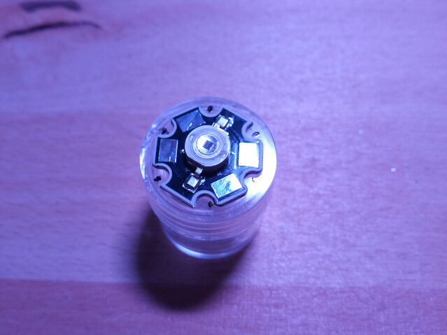
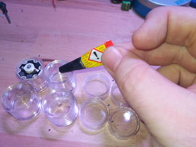
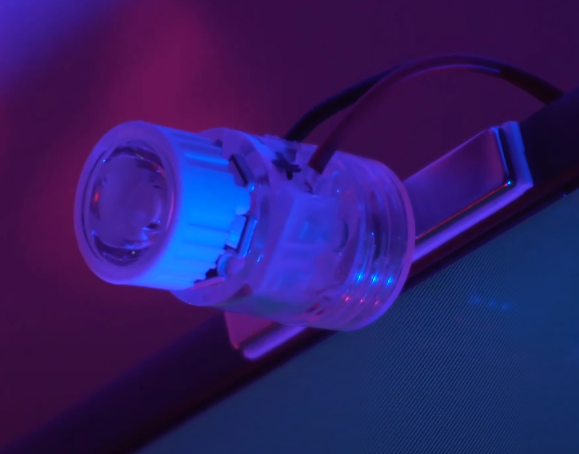
2. LEDs > superglue
Now superglue the LEDs. Be careful not to cover the holes and glue the holes that you can reach the +ve and -ve pole when you put cables through it.
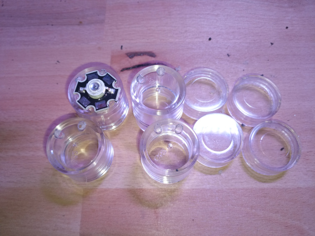
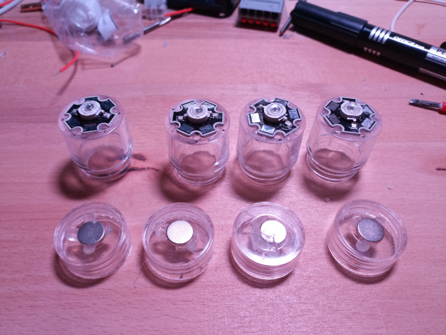
3. LEDs > glue magnets
Now put the magnets in the screw cap. Ensure that the magnet pole faces in the same direction as the others. Put it in place with hotglue.
4. LEDs > Glue lustre terminal in and connect
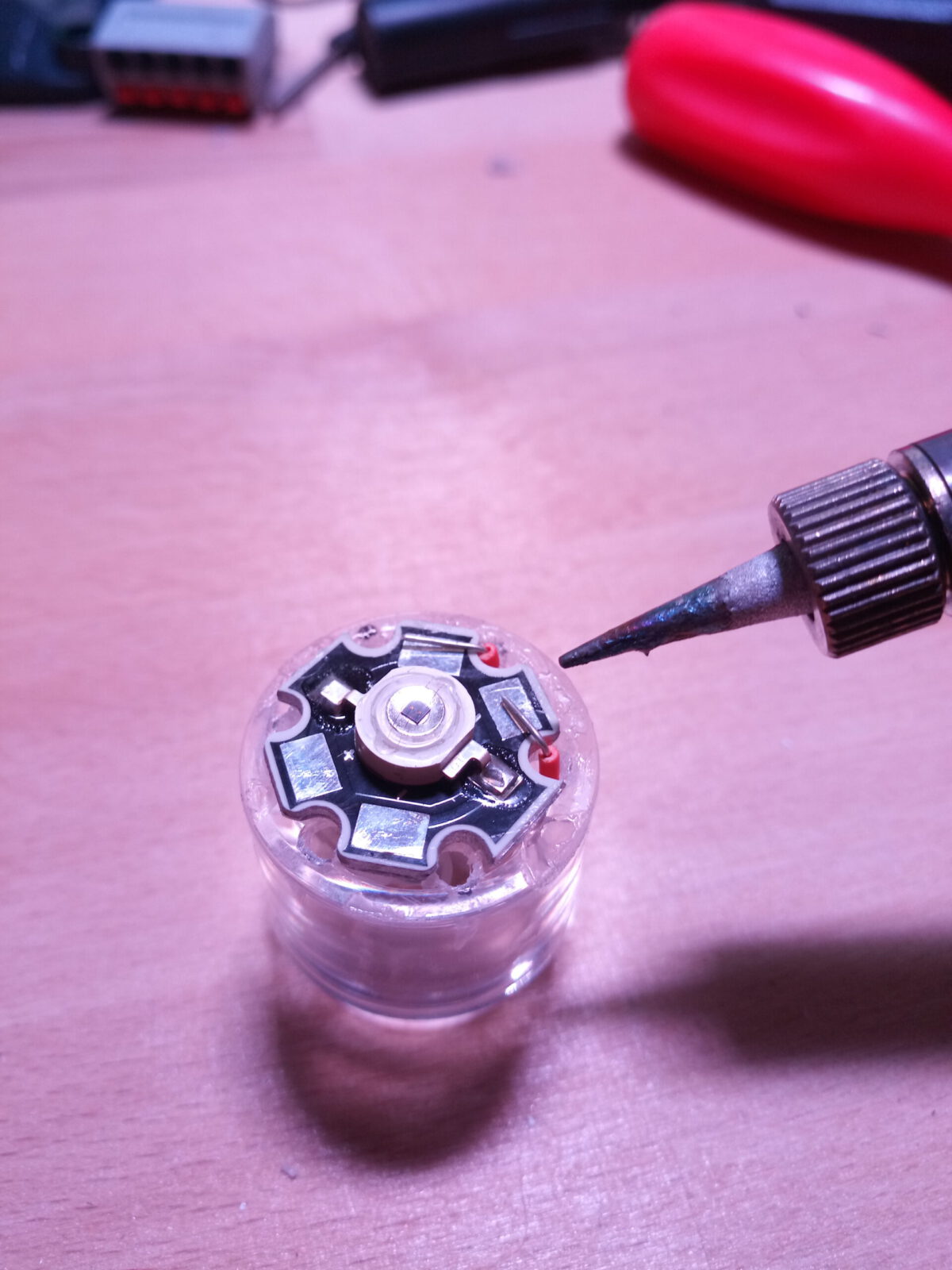
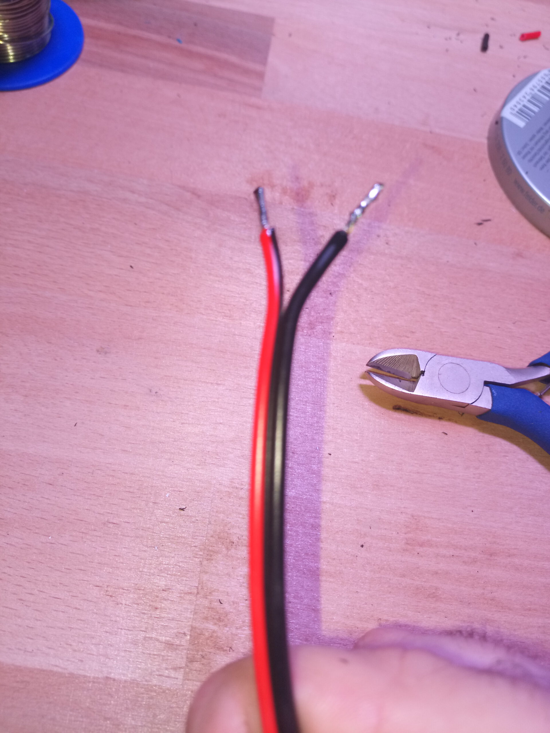
Two pieces of a lustre terminal will be cut off. Connect 10mm electronic cable and connect this to the lustre terminal. Put the cable and lustre terminal in the case, so that the cables go through the holes. If needed cut off some plastic. After this solder the cables to the LEDs.
Put the lustre terminal in place in the case and hotglue it. But ensure that the screws can still be accessed in the future.
When the hotglue is cold mark the holes for the screws which are not connected with black edding. Then drill two holes in the case where the free holes in the lustre terminal are.
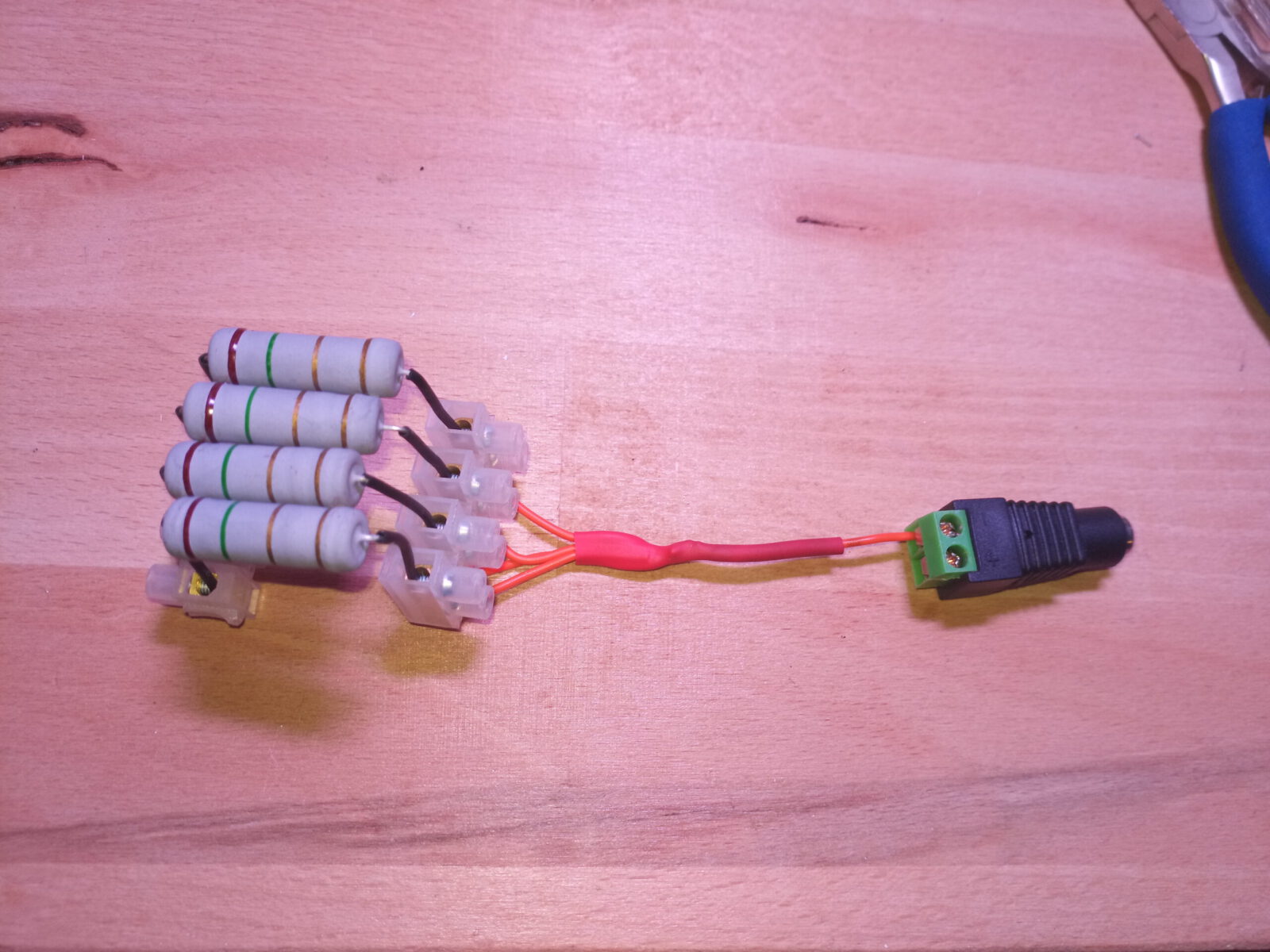
4. distribution box > resistors
- Screw the LEDs together. The Leds should go in the same directions. (Look at the colours).
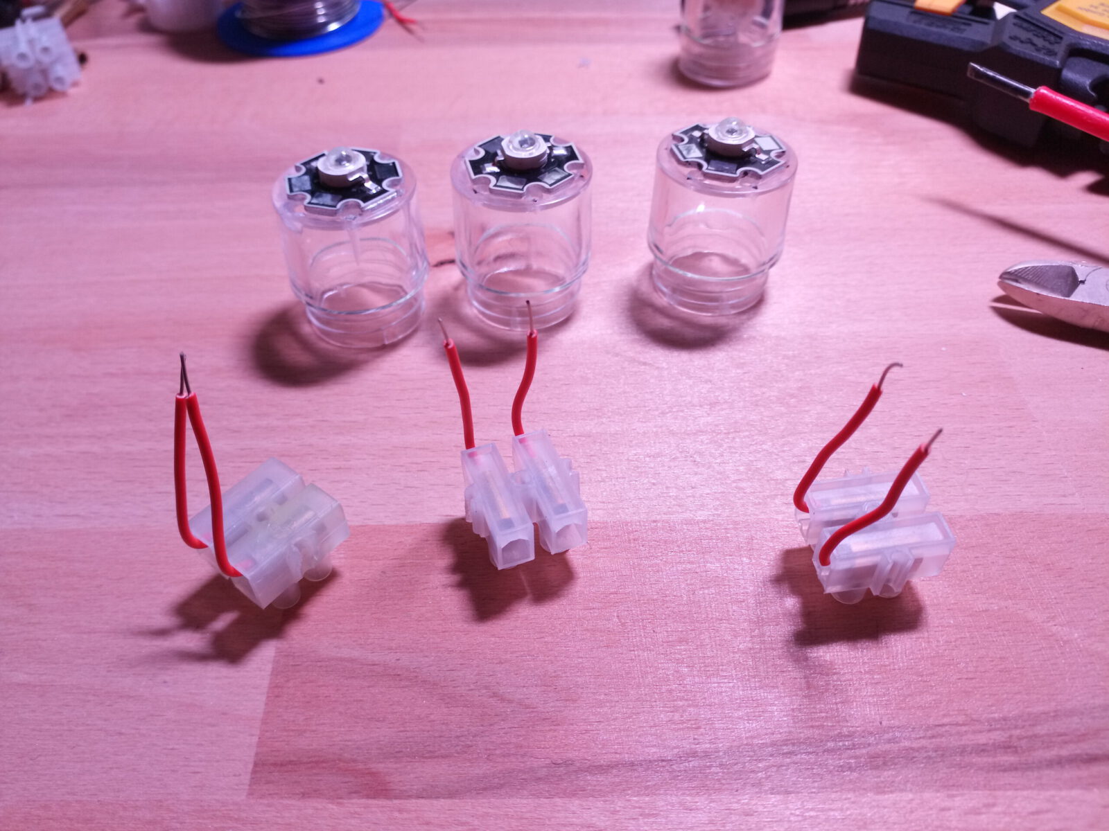
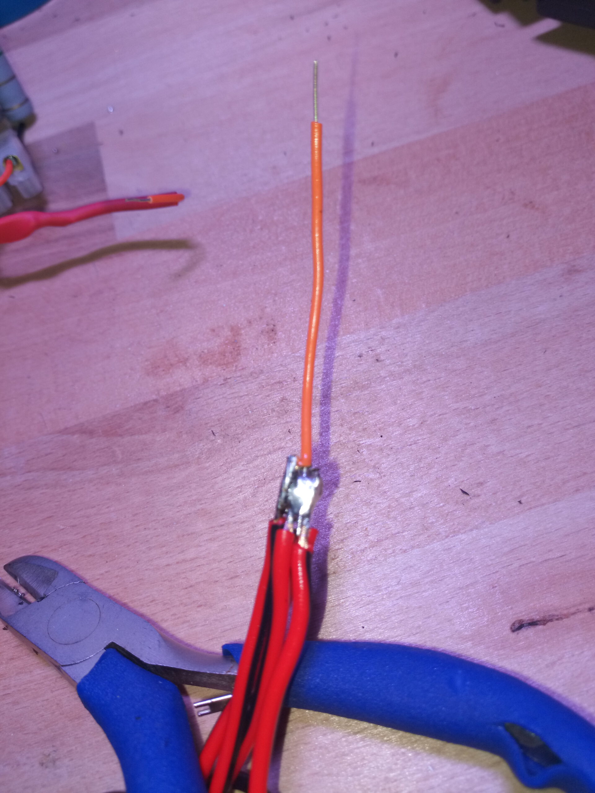
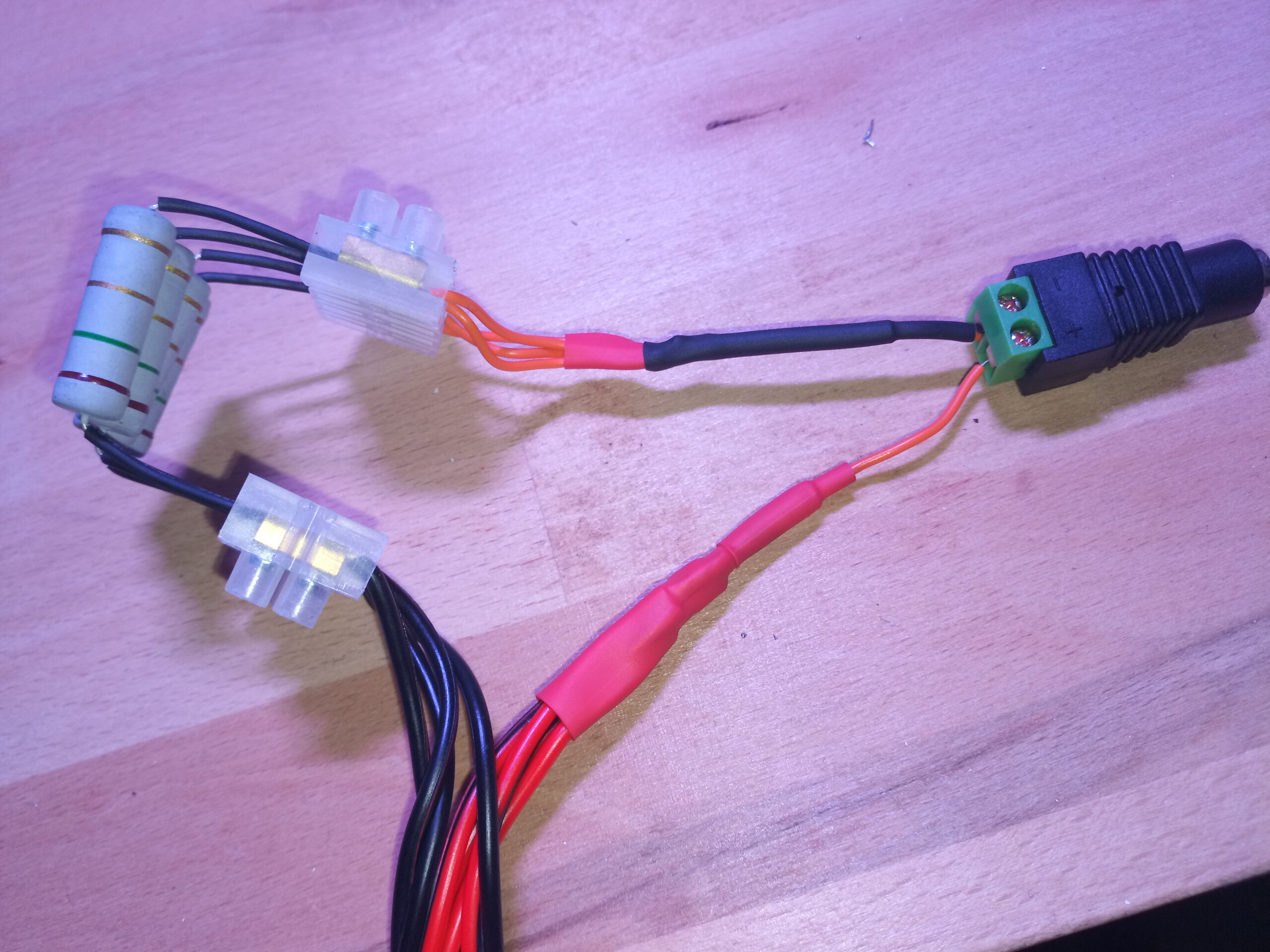
- Prepare the electronic cables like as image 3.
- Secure the cable with cable tie. Use black tie because it will become -ve pole. Not like in the picture.
- Screw the cable to the -ve pole on the power adaptor and the other cables to the lustre terminal.

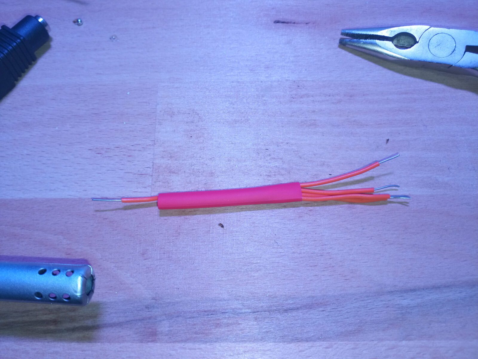
4. distribution box > prepare long cables
- Cut off 4 cables. I would suggest 2 Meters, so its easy to use a beamer.
- Solder the red cables on one side together. Look at image 3. Secure all with a cable tie. Screw it to the positive (+ve) pole of the power adoptor.
- Screw the black cables to the free lustre terminal.
- the other side of the cables should be soldered so that it is easy to screw it to the LEDs.
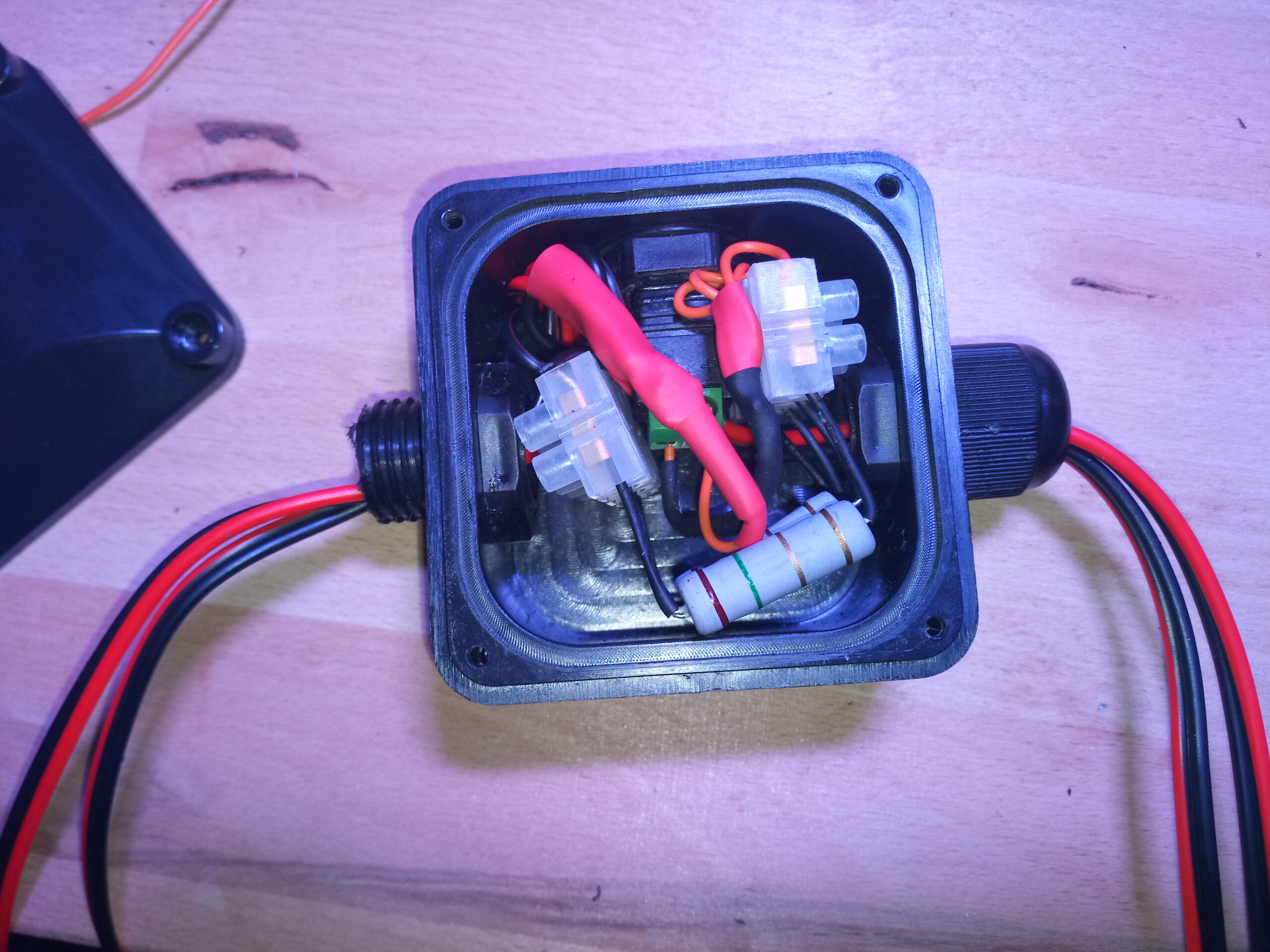
4. distribution box > Put everything in the box
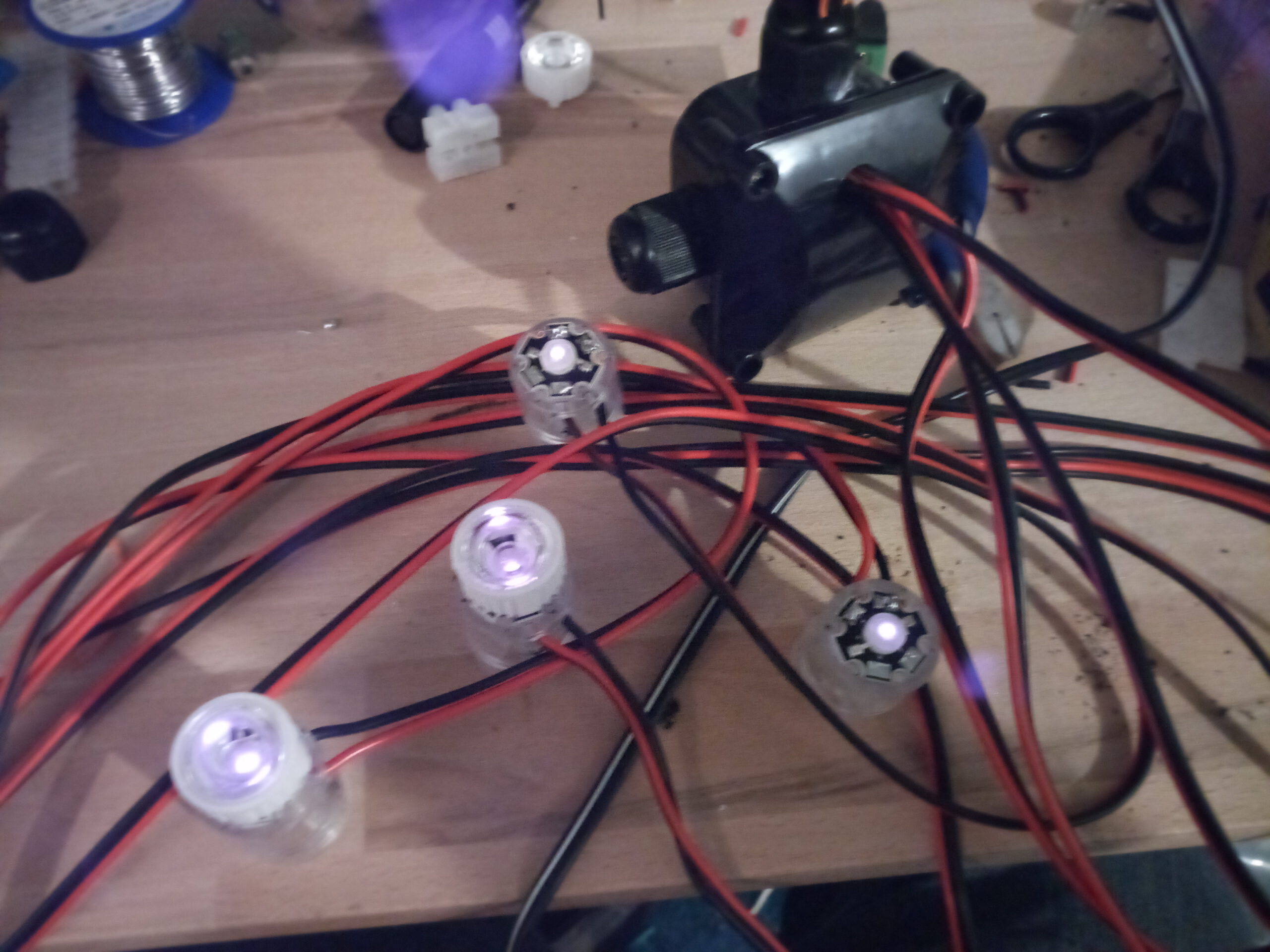
Pack it all in the box as I did. Put the lenses on the LEDs and than you’re ready to go.
CAUTION: Only test the circuit if the box is closed. Do not touch the LEDs when they are under power. There is no warranty for anything that goes wrong.
Tutorials from other Users
- https://diylightgun.com/lightgun-details/?lgid=155#hardwaretab
- Low power LED holder with lens mount by Dragar:
Hey, why do i still see the light coming from the LEDs? Have i done something wrong? I used the 850nm LEDs from eBay and followed your guide. I dont see the leds light in your Video thats why i ask.
Hi,
it is no problem. These LEDs emits some visible light also. Should be maximal minimal light red light. If not than maybe the seller send you wrong items. IDK.
Greetings